|
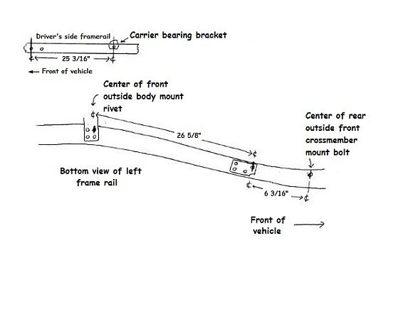
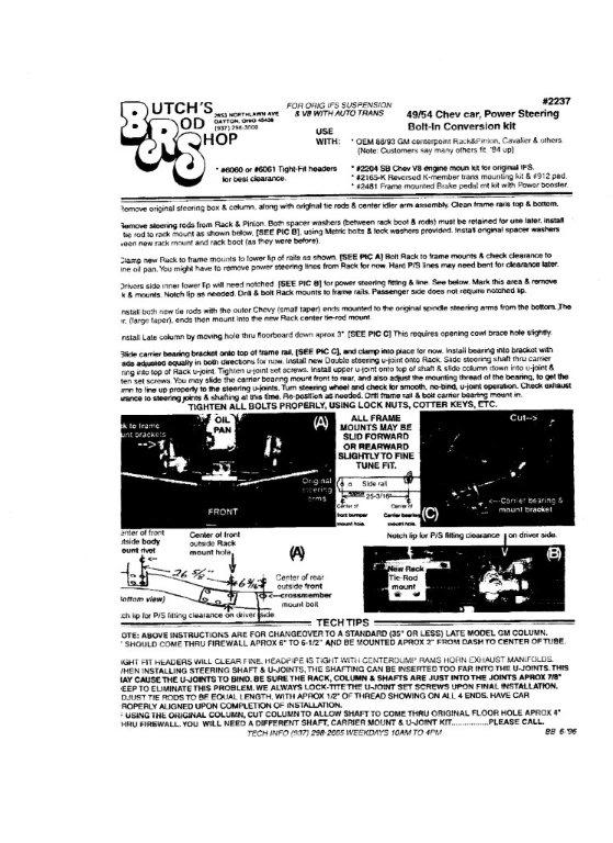
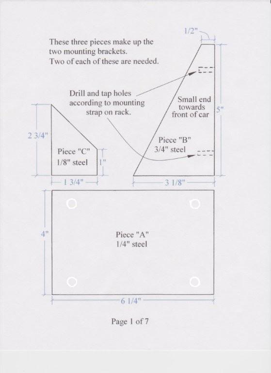
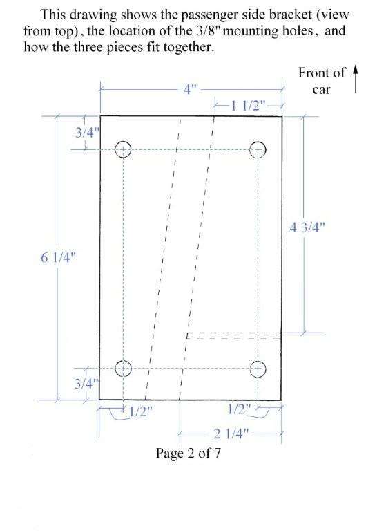
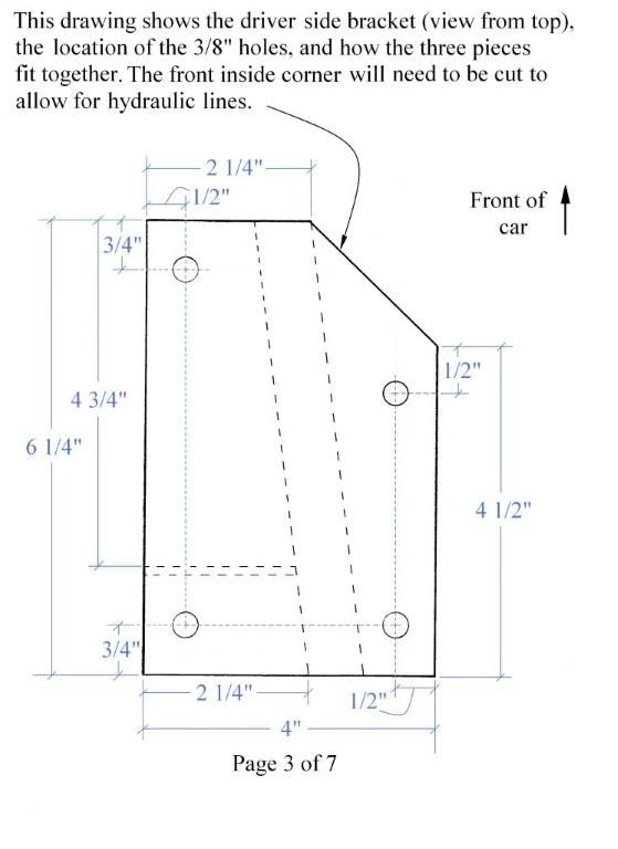
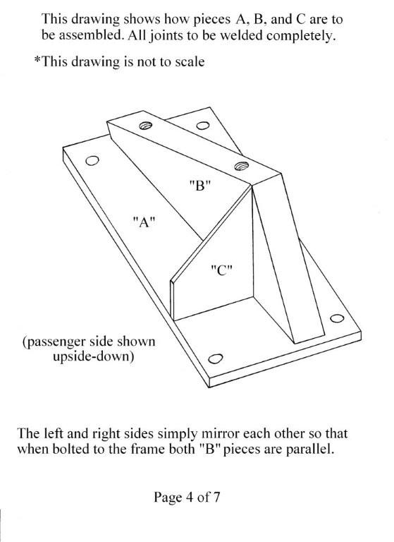
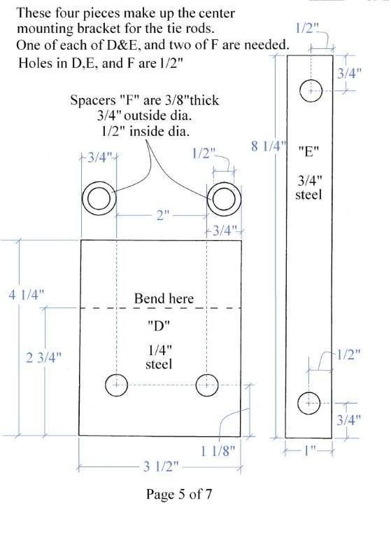
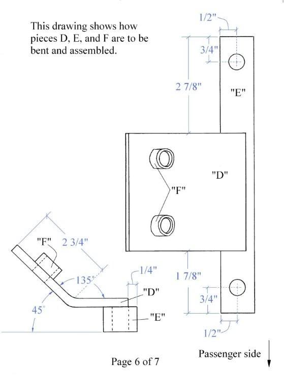
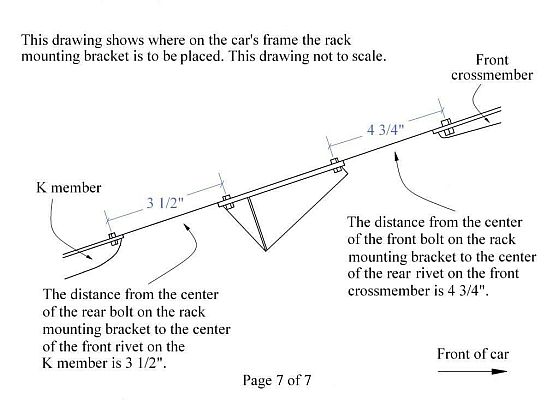
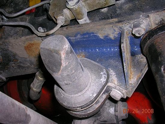
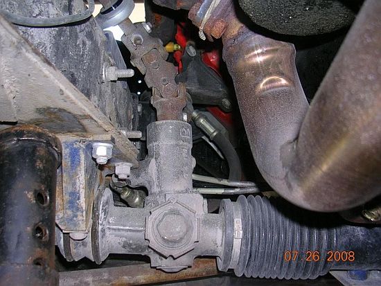
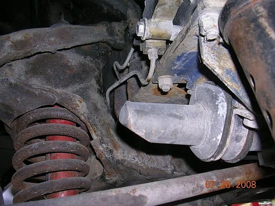
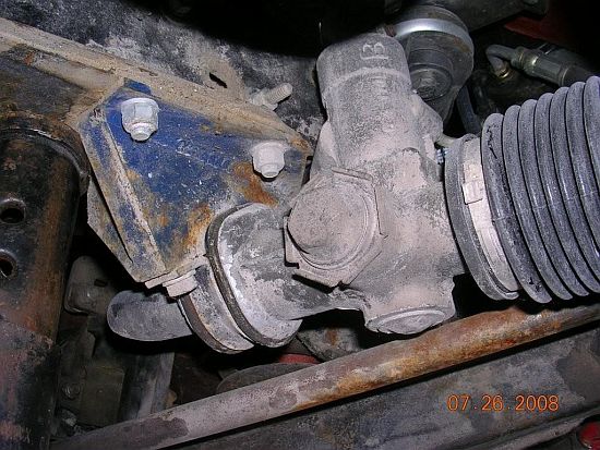
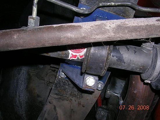
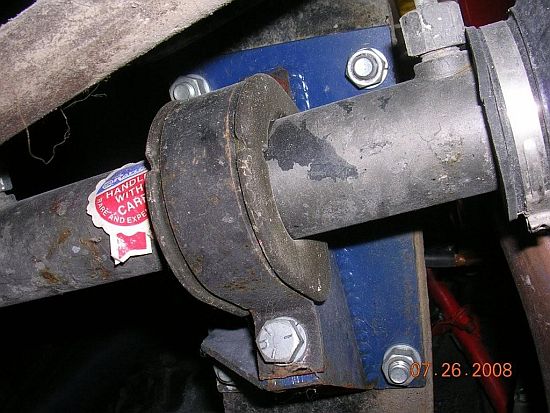
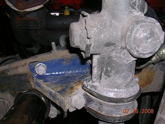
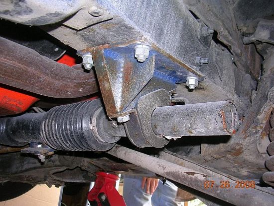
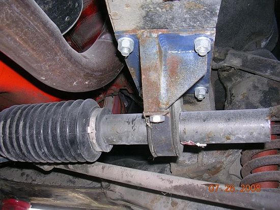
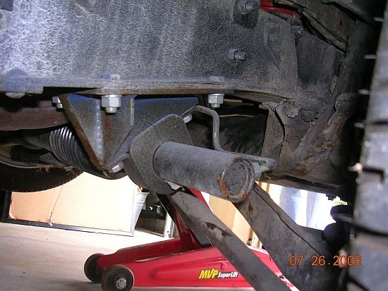
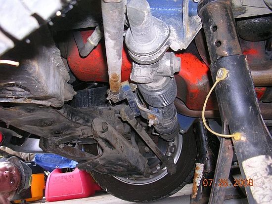
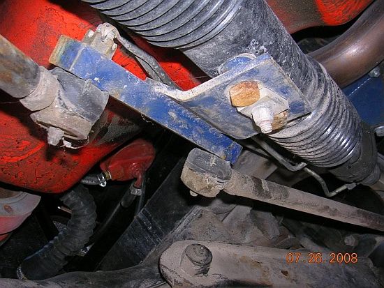
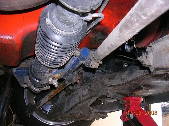
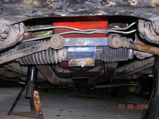
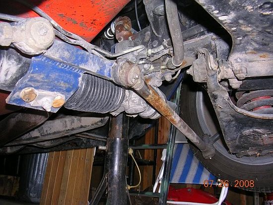
Rack and Pinion Conversion on a 1949 to 1954 Chevy Carby J53 1949 to 1954 Chevy car Rack and Pinion Conversion kit to be used with Chevy small block V-8 engine and a standard late model GM steering column (35" or less) only. Rack & Pinion unit... Use an OEM center point rack and pinion from 88-93 Chevrolet Cavalier or equivalent. Use tight fit exhaust headers for best clearance Use weld on or bolt on aftermarket doughnut type motor mounts. ______________________________________________________ Disassembly / Assembly instructions - Remove original steering box & column along with original tie rods & center arm assembly and discard. Clean frame rails top and bottom. - Remove steering rods from Cavalier rack & pinion. Both spacer washers (between rack boot and steering rods) and metric bolts must be retained for use later. - Install Rack Tie Rod Mount to rack and pinion assembly using metric bolts & lock washers. Install original spacer washers between new rack mount and back boot (as they were before). - Clamp new Rack to Frame Mounts to lower lip of right and let frame rails as shown using the location point 6-3/16" from the front cross member and 26-5/8" from the location point on the outside body mount bolt. Run tie rods to steering arms and check for clearance with the oil pan. The right side tie rod may be in alignment with the oil crossover line on the rack although the tie rod should not interfere with the oil line under normal use. HINT... 2" dropped spindles will increase the distance between the rack and the fitting, plus the 2" drop on the front end looks cool. DO NOT cut the front coils to lower the car. This is not only dangerous, but it will not increase the clearance distance between the tie rod and the right fitting on the rack. -The driver's side inner lower lip on the frame rail must be notched to allow clearance for the power steering line. If you notched the left Rack to Frame Mount, simply trace the same line on the frame rail lip and grind out the notch. The right Rack to Frame Mount does not need to be notched. -Once the brackets are aligned, drill holes into the frame using the holes in the Rack to Frame Mounts and bolt the brackets onto the frame rails and remove the clamps. - Reinstall both new tie rods with the outer Chevy (small taper) ends mounted to the steering arms from the bottom upward. The inner (large taper) tie rod ends mount to new Rack Tie Rod Mount. -Install the new steering column by moving the hole through the floorboard down approximately 3 inches. This requires opening the cowl brace hole slightly. -Slide carrier bearing bracket onto top of frame and clamp into place temporarily. It should be mounted approximately 25-3/16" from the center of the front bumper bracket mounting hole on the frame. Install bearing into bracket with threads equally in both directions for now. Install new double steering U-joint into the rack. Slide steering shaft through the carrier bearing into top of rack U-joint. Tighten U-joint set screws. Install upper U-joint on the steering column end of the steering shaft and slide the steering column onto the remaining end of the U-joint. Securely mount the steering column to the firewall and instrument panel (or bracket). Next, slide the carrier bearing mount forward and backward and adjust the bearing itself outward or inward to get the steering shaft to line up and eliminate any binding. Turn the steering wheel full right and full left checking that there is no binding, that the alignment is good and there is no interference with the headers. Once satisfied, drill holes to mount the carrier bearing bracket to the frame and bolt it in. Check that proper alignment remains and adjust the carrier bearing out or in as needed. Once satisfied that there is no binding, tighten down the carrier bearing. HINT... The mounting holes in the frame rails for the carrier bearing bracket can be drilled larger than the holes in the bracket itself. This will provide some fore and aft movement for the final adjustment of the bracket. Be sure to use large washers and lock washers on the bolts that hold the carrier bearing bracket to the frame. TIGHTEN ALL BOLTS PROPERLY, USING LOCK NUTS, COTTER KEYS, ETC. USE THREAD LOCK ON ALL OF THE U-JOINT SET SCREWS These instructions are for the changeover to a standard (35" or less) late model GM steering column. The steering shaft should come through the firewall 6" to 6-1/2" and be mounted 2" from dash to the center of tube (column drop). Tight fit headers should clear. Head pipe is tight with center dump ram horn exhaust manifolds. When installing steering shafts into the U-joints, be careful that the shafts are not inserted too far into the U-joints. Doing so may cause the shafts to bind on the U-joints as they rotate. Use thread lock on all U-joint set screws. Tie rods should be adusted so that they are equal length with 1/2" of thread showing on all 4 ends. Have car properly aligned by a service technician upon completion of the installation. Additional parts needed: 88 - 93 Cavalier rack and pinion, power steering hoses, steering shafts, U-joints, carrier bearing, carrier bearing bracket, mounting hardware (grade 8 are recommended).
Return from Rack and Pinion Conversion to Suspension
|